20 Led Roulette Wheel Circuit
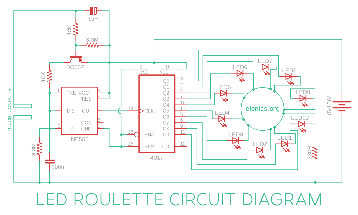
Led Roulette Circuit Using 555 Timer 4017 Ic Elonics
Electronic Roulette Wheel With 20 Led S And With 36 Led S
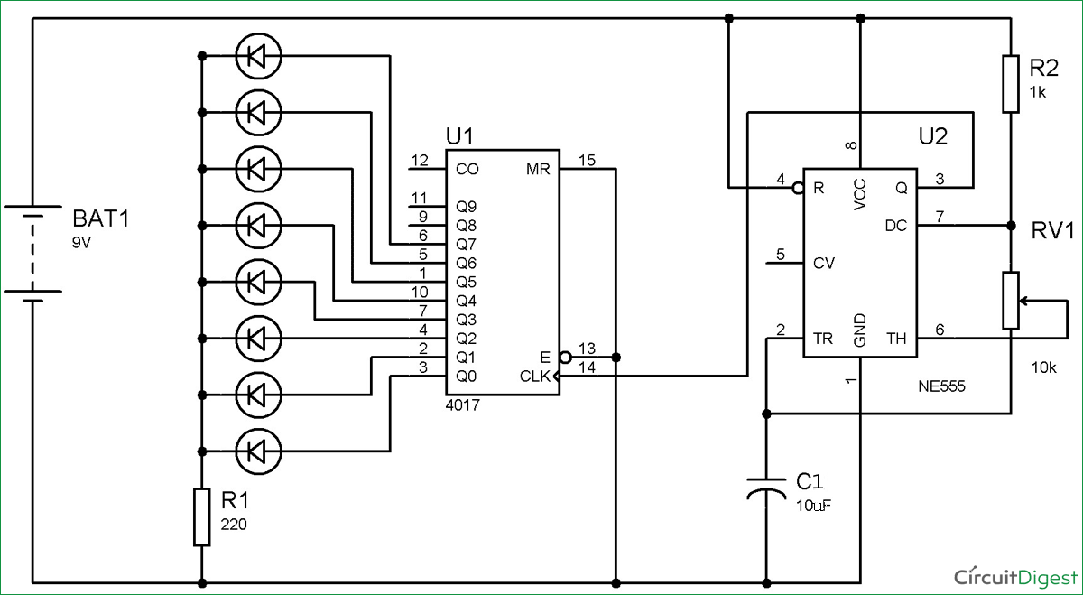
Led Roulette Circuit Diagram Using 555 Timer Ic

Kd 3939 10 Led Simple Roulette Wheel Circuit Diagram Electronic Circuit Wiring Diagram
Wheel Of Fortune Game Circuit

Best Roulette Led Circuit Using 555 Timer Ic Led Blinker Circuit Diagram Electronic Projects Power Supply Circuits Circuit Diagram Symbols Audio Amplifier Circuit Pdf Engineering Projects
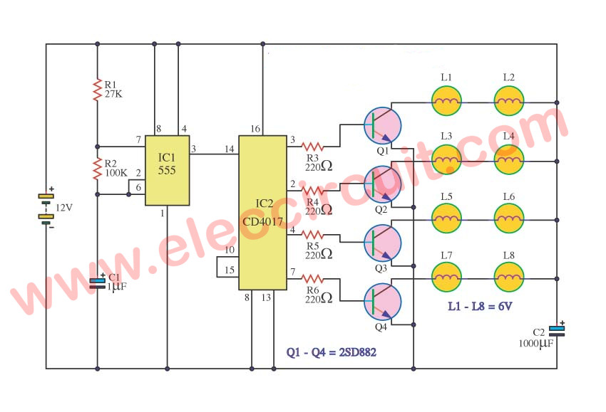
Flashing led roulette circuit diagram using 555 timer 4017 ics.
20 led roulette wheel circuit. In order to simplify but also making the realization of this project much more interesting we took advantage of our dear old digital logics ttl cmos however in order to keep up with the times we will use their modern versions which are hcmos 74hcxxx. Roulette wheel with 20 light emitting diodes in this electronic roulette wheel see fig. The circuit of a simple roulette game presented here is surely one of the simplest as far as the electronic casino home games are concerned. 555 lucky rotary suite electronic diy kit led roulette wheel devin watson.
Control unit and led panel. Subscribe subscribed unsubscribe 171. 1 the timer 555 works as a generator of pulses with fading frequency. This circuit consists of a timer ic and a special ic called cd 4017 which is a decade counter.
There is a casino game and a french word accompanying it called roulette. Now we will connect the leds in a roulette design circle shape as we used 8 leds which are connected by the output pins of the 4017 ic according to the sequence of output start from zero and goes up to 10 but we are using only 8 output pins as the number of leds are 8 and its gets the clock pulse or pulse input from the 555 timer ic in astable mode. Top 20 acoustic guitar intros of all time duration. This led roulette circuit can also be used as an led dice.
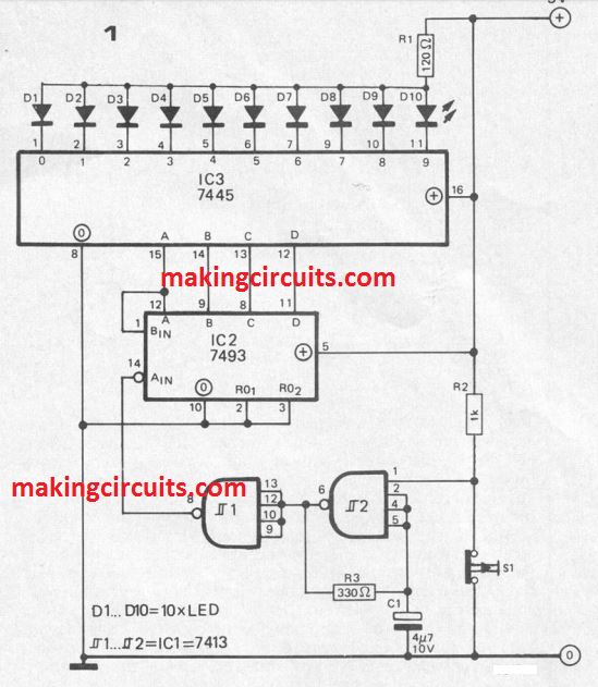
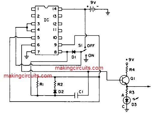
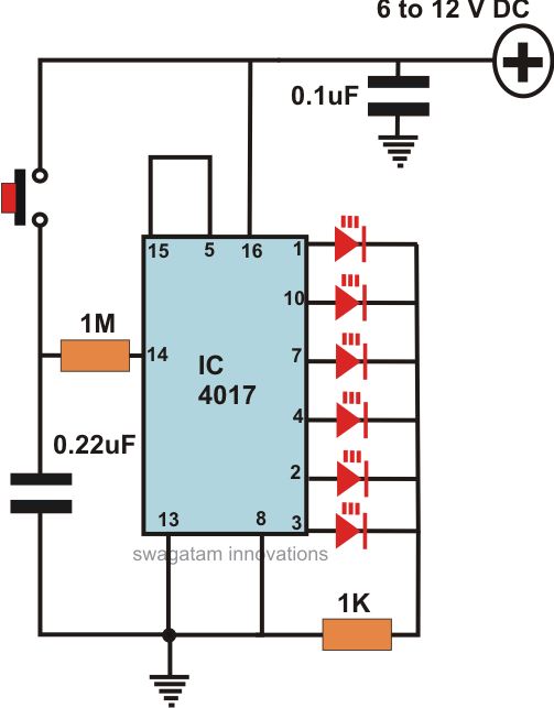
10 led simple roulette wheel circuit last updated on july 27 2019 by swagatam 14 comments a very simple 10 led roulette wheel circuit is shown here. To use only 6 led s instead of 10 you can disable outputs 7 8 9 10 outputs of 4017 ic by connecting its 7th output of 4017 ic to its reset pin via a 10k resistor. To learn more just follow the instructions to build your own simple electronic game also find out how the ic 555 is configured as a voltage controlled oscillator vco to produce a real roulette wheel effect. Arduino led roulette game easy to make.
Unsubscribe from devin watson. So the moment the 7th output turns on it resets the ic and the output switches back to 1st led. Working of led roulette circuit. Pressing the button starts the leds in a rotational motion sequencing at full swing initially and gradually slows down until it stops to a particular randomly selected led.
The electronic part of our roulette is divided in two boards. To build an electronic roulette style led setup i have this part complete that when the light stops on a random led a relay that corresponds to that particular led will trigger this i need some guidance with so it consists of 4 lights hooked up to an arduino uno on pins 5 8 11 and 13 a push button momentary switch is setup on pin 2.
Led Chaser Circuit With Pcb Layout Running Lights Eleccircuit Com
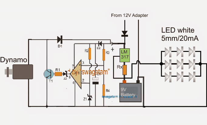
Rechargeable Led Lantern Circuit Using Dynamo Homemade Circuit Projects

Pin On 555 Timer Circuits

Led Roulette Game Roulette Game Arduino Arduino Gps

Https Encrypted Tbn0 Gstatic Com Images Q Tbn 3aand9gcsxvg03ug04hvdcknjicqjfhayha8wa868yyw Usqp Cau

Velleman Mk119 Roulette Poker Table Decor Roulette

Simple Led Voltmeter Circuit Using Lm3914 Eleccircuit Electronic Circuit Design Electronics Projects For Beginners Electronic Circuit Projects
Small Easy Circuit Projects

How To Make A Running Leds Circuit A Professional Looking Pcb 0 2 Youtube Basic Electronic Circuits Electronics Projects Circuit
Results Page 28 About Cmos 4013 Oscillators Searching Circuits At Next Gr

30 Led Projects Led Projects Electronic Schematics Electronic Circuit Projects
Game Electronic Circuit Page 3 Other Circuits Next Gr

Amazon Com Gikfun 60 Seconds Diy Electronic Timer Kit For Arduino 61 Red Led Ek1904 Home Improvement Diy Electronics Red Led Arduino

Pin On Electronice
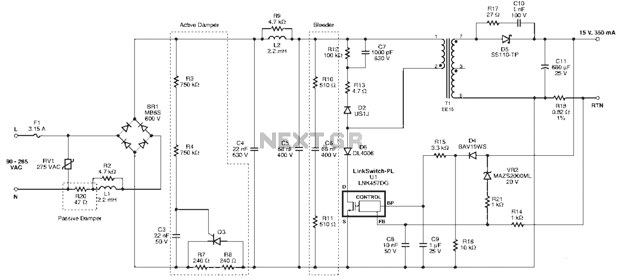
Linkswitch Pl Series Led Driver Circuit Under Led Circuits 57881 Next Gr

Ejemplos De Circuitos De Led Docsity

Pwm Based Led Dimmer Using 555 Circuit Block Diagram Working Led Dimmer Circuit Diagram Electronics Circuit

Simple 220v Mains Indicator Led Circuit Diagram Electronic Schematics Circuit Diagram Led
Https Encrypted Tbn0 Gstatic Com Images Q Tbn 3aand9gcteyqijrhllvystkxh9g3pv48 Ukhliooq Fa6gesbp Rg2eyji Usqp Cau

40 Watt Led Pwm Controll Circuit Diagram Circuit Diagram Circuit Projects Led Lighting Diy

Simplest 100 Watt Led Bulb Circuit Homemade Circuit Projects Led Bulb Led Bulb Diy Electronic Circuit Projects
Converting A Dead Cfl Into An Led Tubelight Homemade Circuit Projects

2019 Latest Emp Slot Jammer For Sale Can Be Used For Roulette Wheel Machines Poker Machine Jammer Card Machine

1 200 Transistor Circuits Electronic Circuit Projects Circuit Electronics Circuit
Top Circuits Page 253 Next Gr
Results Page 348 About Stereo Switch Circuit Searching Circuits At Next Gr

Mosquito Repellent Circuit Mosquito Repellent Circuit Using 555 Timer 555 Timer Youtube

33f Fig 1 Led Lighting Circuit For Christmas Jpg 678 373 Pixels Led Christmas Lights Led Transistors

How To Make A Simple Led Automatic Day Night Lamp Circuit Homemade Circuit Projects Electronic Circuit Projects Circuit Projects Electronic Gadgets For Men

Simple Basic Led Circuit Circuit Diagram Led Projects Diy Electronics Circuit Diagram
Electronic Circuits

Touch On And Off Switch Circuit Diagram And Working Circuit Diagram Electronic Schematics Electronics Circuit
30 Led Projects

Simple High Power Led 10w 12 Volt Driver Circuit By Using One Transistor And Other Cheap Components See Circui Led Drivers Power Led Motorcycle Led Lighting

Amazon Com 8 Gang Switch Panel Teochew Led Universal Switch Box With Circuit Breaker On Off Switch Panel For Boat Jeep Truck Car 4x4 Automotive

How To Calculate The Value Of Resistor For Led Led S Circuits Led Resistors Circuit
Results Page 336 About Solder Station Circuit Searching Circuits At Next Gr

Metal Detector Circuit Electronic Schematics Diy Electronics Electronics Circuit

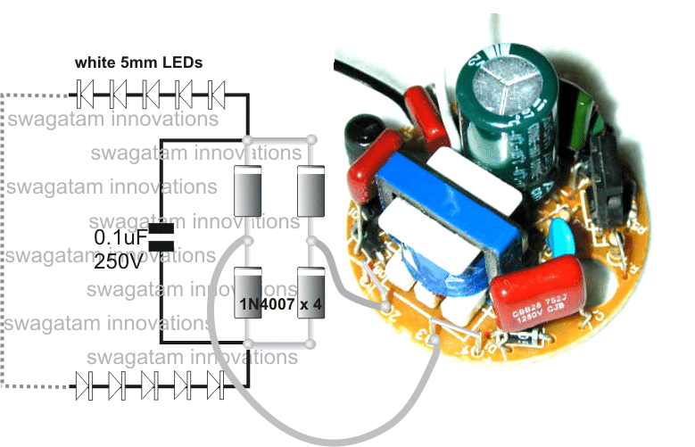
Ac Powered 220v Led Circuit Led Lamp Diy Electrical Engineering Projects Led

Do 0209 Up Down Fading Led Circuit Download Diagram
Tamil Electronics Com Ne 555

How To Use Led Circuit In Basic Ways Eleccircuit Com Basic Electronic Circuits Electronic Circuit Projects Circuit Theory

How To Make Led Chaser Very Easy Circular Led Chaser Running Led S Led Led Cube Arduino Led Matrix

